Saturation Current Tester
With my PWM GTI project still ongoing I noticed that its toroid inductor (not the transformer) runs rather hot. This is due to the core saturating. This is bad as this causes significant losses (heat). So I decided to examine the saturation behavior of my coil. Now, there are many designs to be found across the interwebs so I decided to create my own version. If not to hone my assembly programming skills.
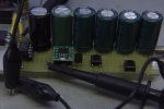
I happened to have a few PIC12F617 devices. These contain a PWM module. My chip comes in a SOIC form factor. I mounted it on a SOIC->DIP adapter (thank you, Mr. Ma) so I could put it in my aging ICD2 programmer. Inspired by the many examples found online I built this tester:
The circuit is straightforward: controller, with its 78L05 regulator, driver (TC4426, should have used a TC4451 but alas, too late) and low R(ds,on) MOSFET. The LUT (Inductor Under Test) is connected via two short pieces of sturdy wire as suggested by Homo Ludens Manfred Mornhinweg on his excellent exposé on the subject. The actual testing takes place by connecting a scope across the source resistor and taking its trigger from the PWM output of the PIC.
As is wont with these projects the firmware (asm file)for the controller caused some head scratching. Setting up the PWM was a bit tricky and the datasheet provided a solution (use the timer2 interrupt to configure the port for PWM). This solved the switching on of the MOSFET after reset. The steps of the UP button were too big, especially at short test pulses so I had to go all flow chart to set the LSBs of the PWM. What really puzzled me is that the inductor current would not go to zero between pulses. This was a "face, meet palm" moment because the current in the coil has to decay before a new pulse starts. Because it is clamped by only a schottky diode forward voltage drop this takes awhile. The resistor across the coil doesn't really do all that much. So I had to increase the PWM period to 4 ms before I got useful results.
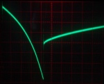
Performance is good:
This test shows that the onset of saturation of my PWM GTI coil is too soon for the switching frequency. Increasing it would solve the saturation issue and the power losses. Hopefully. The capacitor bank is up to the task: voltage droop is only 0.4 V which is perfectly acceptable. The smaller steps at short pulse times allow me to test low inductance coils. All in all I'm very pleased with this result!
Back to the homepage
Date: 1 September 2019

This software is licensed under the CC-GNU
GPL.


