


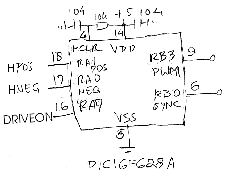
Not satisfied by the crude operation of my GTI I decided to drive the transformer with a sine wave, like any self-respecting GTI does. What better way to create a sime wave than with a PIC! At first I tried to generate a PWM signal with a PIC12F629 but as this chip doesn't have a PWM module I had to change to a PIC16F628A. I have way too many ports now so I could rewrite my code for a PIC12F617 that does contain a PWM but at the time that was all I had.
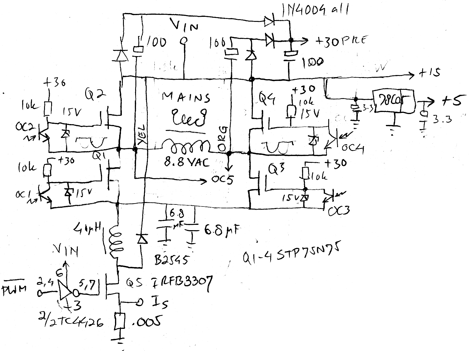
But first I needed new hardware. I wanted to keep the existing toriod and the meter circuit. After some headscratching I decided on using an H-bridge and a PWM to voltage converter using a simple form of buck topology. The H-bridge is driven by the PIC as well via opto couplers. Since it only switches during zero crossing the optos are fast enough. The PWM output switches at 20 kHz. The chosen transistor (the one I found in my tray, just like about everything else) has a large C(in) (5.2 nF) so it needs a high current driver (TC4426) to keep losses to a minimum.
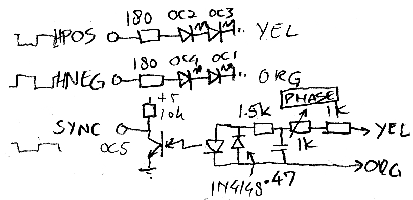
During code development I ran into several issues. The first was fatal lockup at startup. The PIC would not run and switch off the optos causing the MOSFETs to go full on. This drained the PIC of power. Eventually this was solved with extra hardware and a PIC output signal (DRIVEON). Then there was the matter of synchronizing the internal clock with the mains phase. The PIC is a bit slower and needs a consistent reference point to properly sync. This is done with a fifth opto. To precisely adjust the phase of the PIC to the mains a lowpass filter/phase shifter is included. So, I now have the PWM drive, HPOS and HNEG for the H-bridge, SYNC to the PIC and DRIVEON for the gate voltage of the MOSFETs of the H-bridge. So yes, it would fit in a 8-pin MCU (PIC12F617) with MCLR available. Too bad the external interrupt pin is the same as the CCP1 (PWM output) pin so I will have to use an IOC interrupt with the additional polarity test. Bummer.
One of the most important features of a GTI is prevention of island operation. When mains power fails the GTI should immediately switch off. That needed quite a few iterations of the code but this was finally solved. Also, proper syncing when connected to the mains and when the external power is supplied now works as required. The whole shebang can be seen in the final code. There are two interrupts, timer0 and RB0. The timer triggers every 0.2 ms and then looks up the next value from the sine table. Which is used four times, for each quadrant of the sine wave. The values are actually the center of each part. Initially I thought that the duty cycle should be far below 100 % but that was just silly and caused me needing more supply voltage than I had available. I finally decided on 99 %. I used a spreadsheet to generate the table.
The second interrupt is driven by opto OC5 and syncs the PWM to mains. There are a few flags used that perform the sanity checks to prevent island operation and syncing when connected to the mains. Because the sequence is complicated and confusing I made a flow chart to figure it out. It works very well and consistently within one single phase. I also pondered on whether to build some hardware panic switch in case of a fault condition like the poweron latchup situation described above but decided to leave that to the mains fuse. My own power source (the homotrainer) doesn't deliver enough power to really damage things so it is not protected.
The electronics was built on a piece of prototyping board that would fit the old GTI.The mains filter was cut off from an old LCD monitor power supply board.
The old controller and MOSFETs were replaced with the new board. The toroidal transformer had the thin wire windings removed. During testing it transpired that my H-bridge transistors wanted to be cooled so I cut off some aluminium L-stock. I then thought it would make an excellent mount point for banana sockets. It does get a bit hot though...


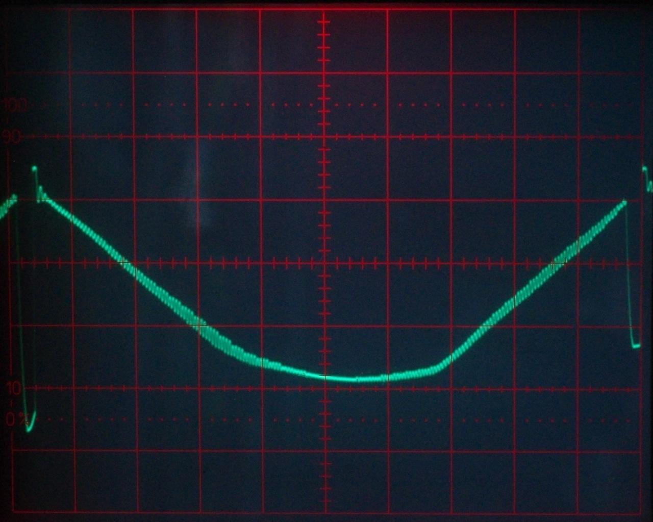
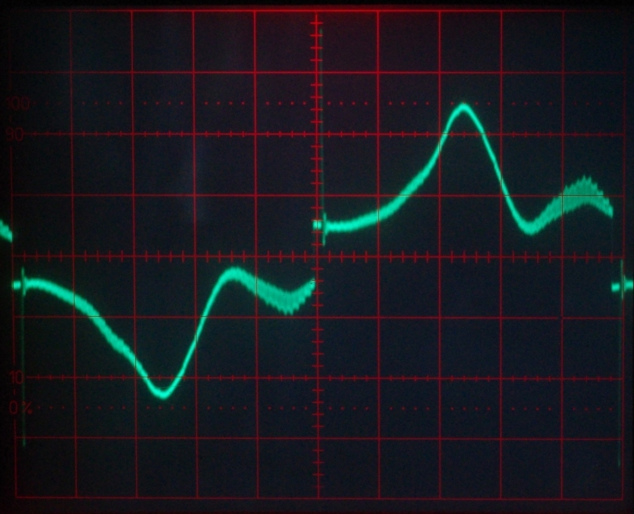
The final test of this contraption was the prevention of island operation and the proper startup when connected to the mains. It took a few attempts to get the shot from the oscilloscope screen right but this shows that it works perfectly. When mains power is lost the circuit tries to synchronize with itself and this causes the criteria for keeping MAINSOK flag set to fail and the H-bridge switches off. PWM remains active, as the little bumps in the second half show.
Reconnecting it to the mains was easier to capture. Top trace shows the SYNC signal, after three periods the circuit is sychronized. This can be clearly seen happening in the timing of the bumps before the H-bridge switches on once FREQVALID flag gets set. The process is shown in the flow chart. Also, the voltage of the power supply can be seen dropping as the load kicks in. The first peak is much higher than the subsequent ones. This was without the big blue capacitor mounted horizontally on the wooden base.


Finally, what bothers me is that the 20 kHz ripple on the PWM output is so high. According to the LTSpice simulation, it should be 1-2 Vpp but it actually is much higher:


I will try to fix this by replacing the two 6.8 µF capacitors with 15 µF units. Should make some difference. Still can't think of the reason, the caps are fine and don't get warm at all during heavy load (110 W feed back power). Could be that the inductive load of the toroid has some influence but could not get this from the simulation. I also observe (no screenshot) that the source current maxes out instead of rising linearly. But as this happens at different levels this can't be core saturation. As this coil is liberated from a fat switch mode power supply this would be unlikely. Maybe the litze wire has something to do with it.
All in all, a nice little project on the side!
Update 31 August 2019:
New insight! I played some more with the LTSpice simulation. I learned that preventing the inductor current to go to zero dramatically reduces the 20 kHz ripple. To do this, its inductance needs to increase. Or the frequency must be set higher. Or both. I replaced the 40 µH litze inductor with a solid wire toroid (96 µH) from another power supply. This helped enormously! See the first piccie below:
However, the second image above shows the current that I'm dumping into the grid. You hardly can call this a sine wave... This means that I'm looking at a second iteration of my PWM GTI. v2.0 if you will. I have the concept in my mind, now I only have to actually realize it. I want to use the PWM modulator to adjust the current into my transformer to look like a sine wave. This means that I will use the sine wave lookup table to compare the current in the source of the power MOSFET. To do this, I need an analog switch (1/4 4066) to sample and hold during the time the MOSFET is OFF. I will also need to change the controller to PIC16F818 because I need an A/D converter. There will be the need to implement some algorithm for MPPT (Maximum Power Point Tracking) so I use all power that is available momentaneously. This is necessary because the PWM control will over- or underadjust when the available power changes. But everything else stays the same. Hardware-wise. I still can add some bells and whistles like indicator LEDs showing the feed-back power level and fault conditions (no mains, no input power). But all that is for later!
Date: 14 August 2019

This software is licensed under the CC-GNU
GPL.