PIC Matrix Scope
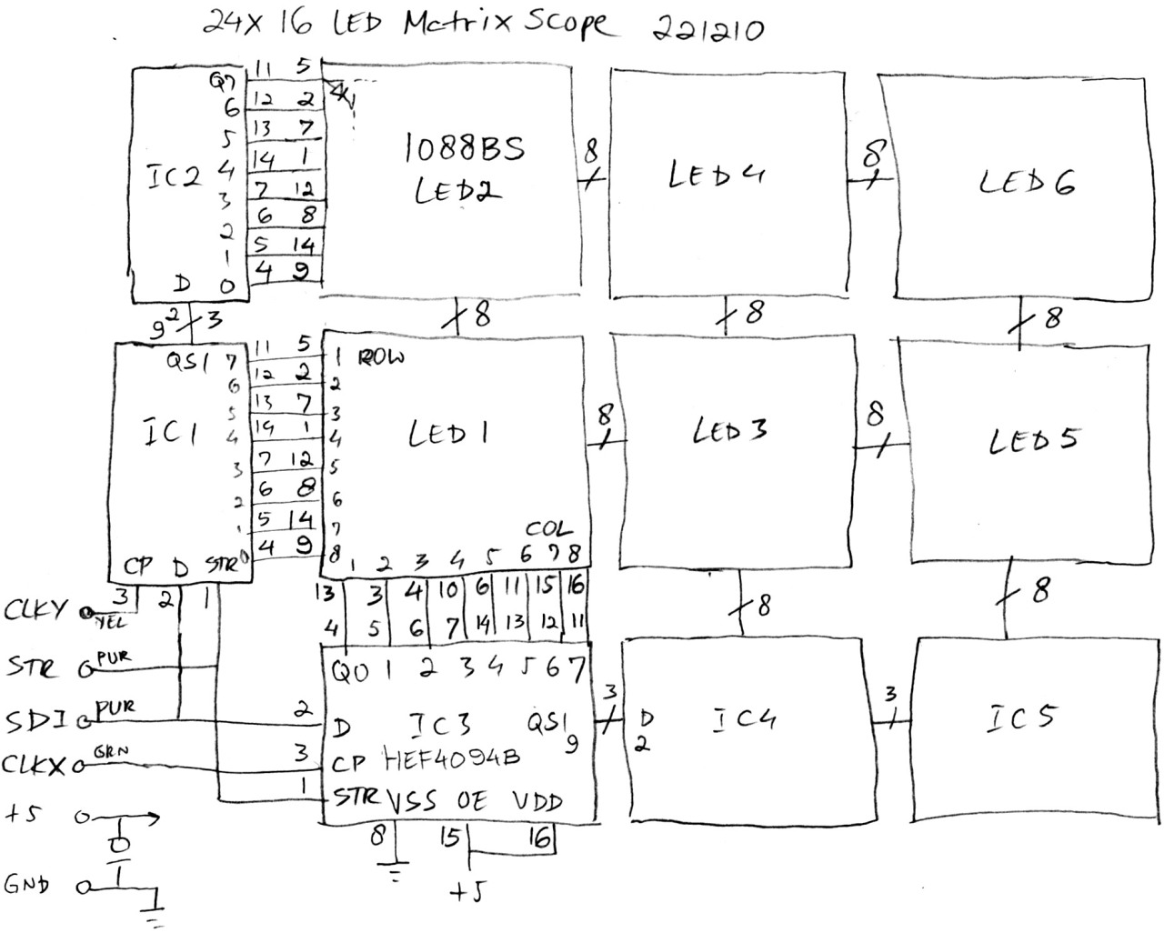
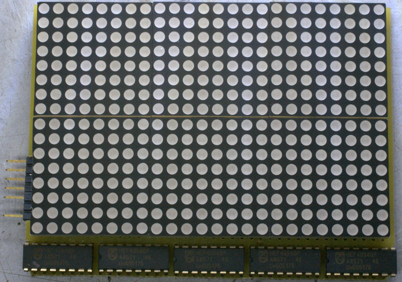
Another one of those brain farts... I was thinking of the shift registers of my 3x5 DCF clock and ended up with them driving a LED matrix to act as an oscilloscope. The concept is simple: write a single ZERO into a shift register to act as the horizontal timebase and a single ONE to show the vertical voltage. As the ZERO is shifted through the horizontal shift register and the voltage value into the vertical shift register this will produce a scan just like a CRT does. I used a surplus board with a PIC16F818 and two buttons as base and added an input amp and trigger generator as a subboard. The matrix display consists of six 8x8 modules which results in a whopping 24x16 pixel scope display:
The code (asm) is straightforward. After the necessary init stuff the main routine gets the input value and, depending on whether the sweep time is ready, displays it. There are two interrupts: timer 0 and RB0. TMR0 deals with reading the buttons for setting the sweep time (UP and DOWN for faster and slower sweep) and RB0 receives the trigger pulse from the input subboard. The Y decode routine could be a bit faster using successive approximation but I kept it simple as there are only 16 values to decode.
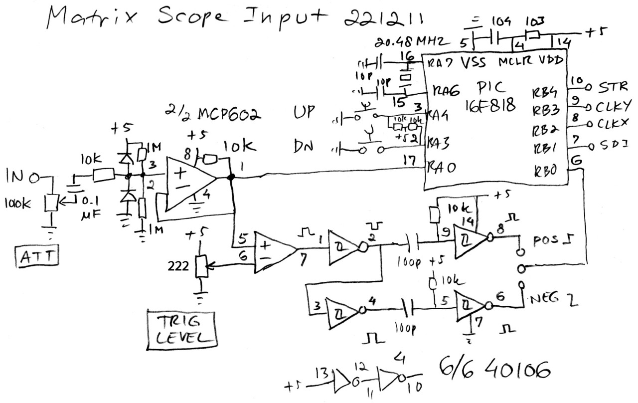
The trigger pulse is generated by an opamp and four inverters and is a short pulse causing an RB0 interrupt:
If the sweep is near completion it will reset and show a stable waveform.
The construction of the display was done on a prototyping board. Lots of Roadrunner wire was used:
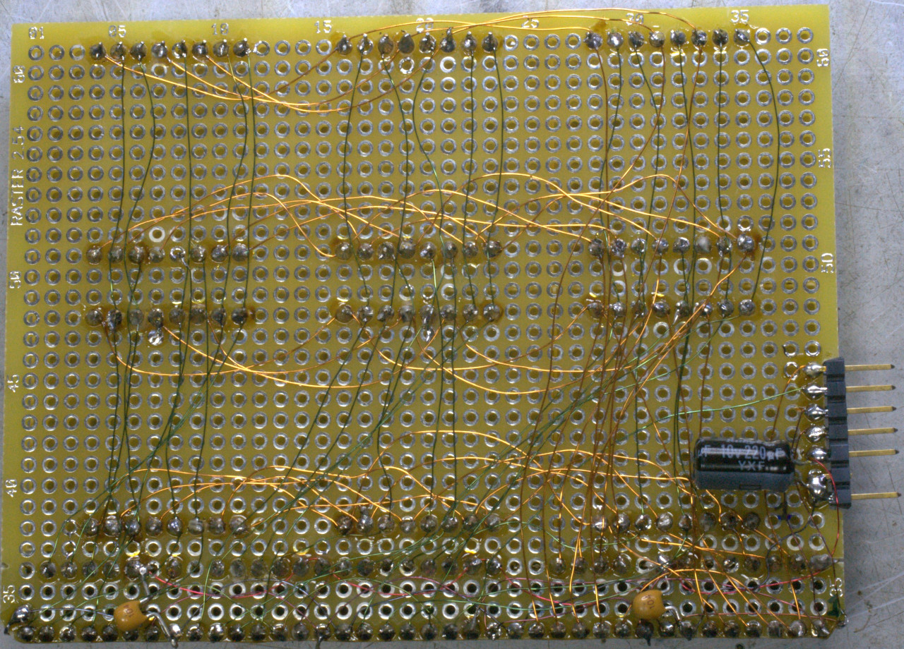
The Eurocard sized board is two holes too narrow to accommodate all five HEF4094s so I kludged extra holes for them. The PIC and subboard are connected with a short cable with a pin strip header.
The input board caused some design issues. Initially I used an LM358 but this is not an R2R (rail-to-rail) device and will not output close to the positive rail (+5 V). So I chose an MCP602 (but any reasonably fast CMOS R2R opamp will work):
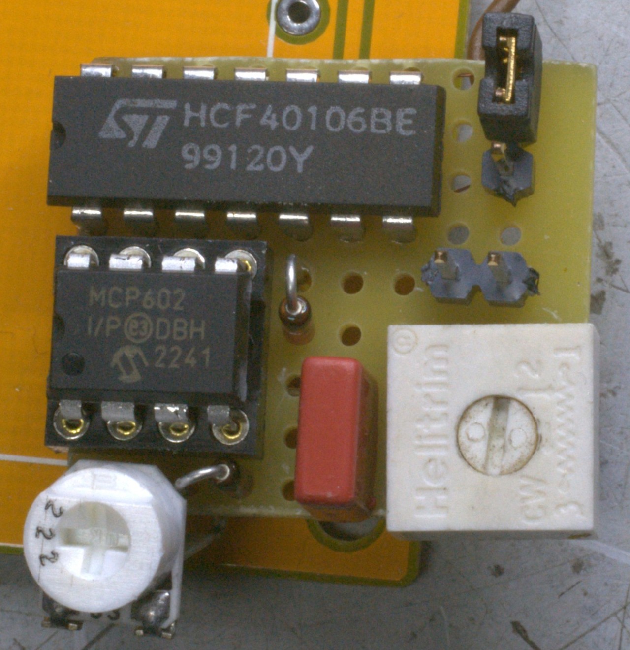
The round trimmer is trigger level and the square one the input level. The jumper selects trigger polarity.
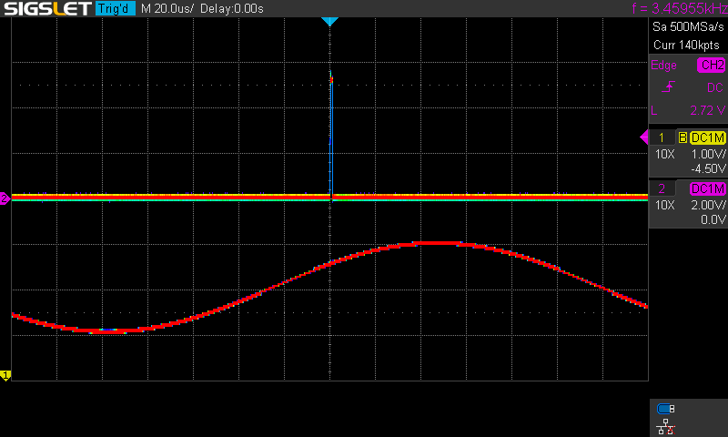
With the clock of the PIC at maximum the performance is not even all that bad. Max frequency is 20 kHz or so, and a square wave looks as it should:


All in all a fun little project!
Back to the projects page
Date: 30 January 2024

This software is licensed under the CC-GNU
GPL.