3x5 Matrix Display DCF77 Clock
I have never seen a clock (or anything else for that matter) with 3x5 matrix displays. So when I gave away the analog clock in my radio room I and needed a new clock I decided to tackle that challenge.
First I made a quick study, to see what I needed:

This still shows the original numbering which I abandoned quickly while developing the code. I counted the LEDs I would need, which was 94. I then ordered 100 of these orange 5x5mm square LEDs. At first I thought that the PIC would be able to drive all rows easily but that idea was quickly abandoned. I then realized that I still had a LED driver IC with 16 outputs. Since I needed 19 columns (3x6 plus one for the colons) I would have needed a second chip. Being the frugal developer I decided to use three ports on the PIC instead:

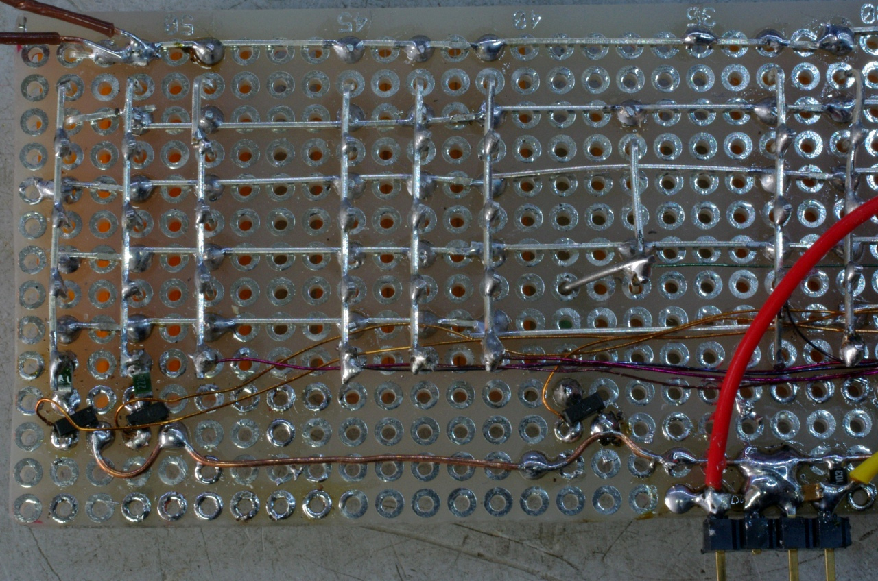
The PIC first drives a row while its data is shifted into the STP16CP05 LED driver. This is repeated for each row. Columns 10-12 (hex) are driven separately. The data for the shift register in the LED driver is taken from five lookup tables. The colon is not looked up because it's either steady (sync'ed) or flashing (unlocked). The original idea was to make a nice light show but that idea was abandoned because it was deemed too complex to implement (with more lookup tables) and because it almost never shows.
The rows are driven from the PIC via P-MOSFETs because the PIC is unable to furnish the needed current. This is set by a resistor on the STP16CP05. The maximum current needed is 19x15 mA=285 mA with is way too much. The electrolytic C is 1000 µF and is needed to cope with changes in current as LEDs are switched on or off. The NDS0605 SOT-23 SMD transistor was in my MOSFET tray and luckily enough I happened to have exactly five. The 2N7002 N-MOSFET (also SMD) I had many more of...
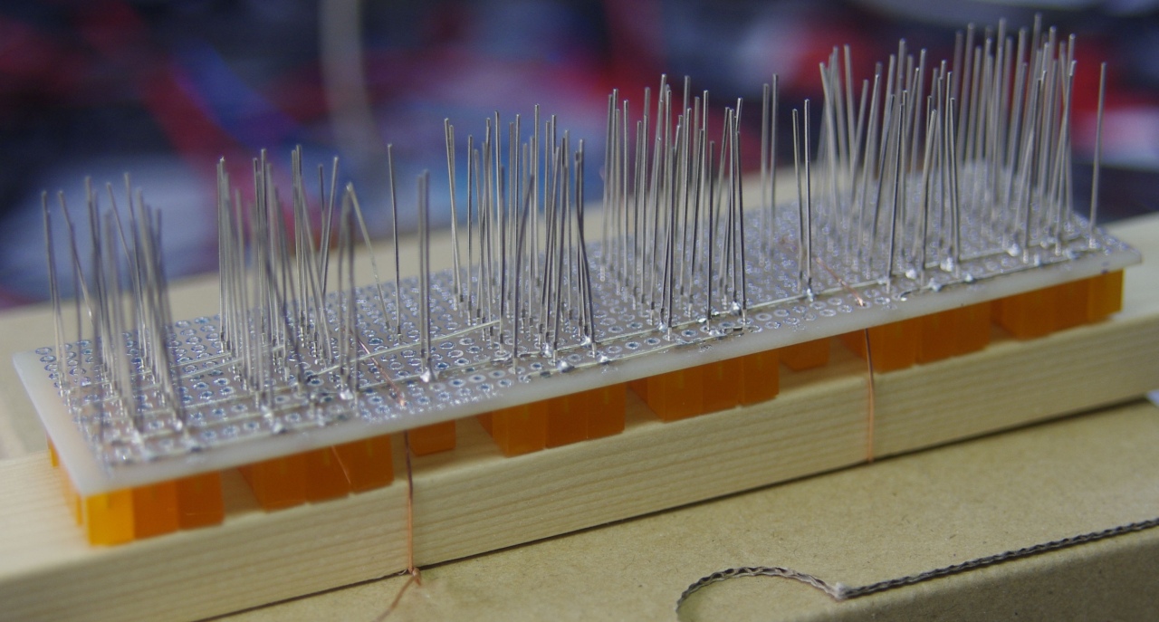
Once the LEDs arrived I had to mount them on the prototyping board. This proved to be a challenge because they tend to fall out of the PCB during assembly. Eventually I resorted to lash the board to a piece of wood:
The code (asm file) for PIC16F628A posed some headaches. As I had had issues with lookup tables before that was easily solved (preload PCLATH). The lookup tables themselves were created quickly, taking in account the shapes of each number. I especially like the form of the numeral 1, which is something you cannot do with 7-segment displays. Another catch was the use of STATUS,Z instead of carry. This caused some weird behavior when the test would pass when it should have failed (test for 59th second). The funniest bug was the mask for the parity check for the hours. It passed until 20:00 after which the time was stuck at 19:59 because the DCFOK flag was kept set. The mask was wrong because there are only six hour bits (01, 02, 04, 08, 10 and 20) and seven minute bits. The txtempus DCF transmitter for Raspberry Pi helped enormously to debug this. Great name too, "transmit time" (in latin). Also the parity check routine that I found here was a great find. My routine would have been much more inefficient.
The code runs solely on interrupts. There are three: DCFHandler, Timehandler and Multiplex. DCFHandler gets triggered from Timer0 and runs every 50 ms. It looks if the DCF input is high or low and decided what to do with the outcome. If it's low it will test if there are pulses at all (DCFLOSS) and then if the preceding HIGH pulse was 1, 2 (DCF databit zero) or 3, 4 or 5 (DCF databit one). If it's longer the DCF data is deemed invalid. After that, the databits are rotated into the minutes- or hours buffer, depending on the count of received bits. If it's high it will test for the 59th second. If this test is OK it will decode the DCF data in the buffers, else it will again deem the received data invalid.
Once the DCF data in the buffers has been rotated into their respective registers (minutes, 10 minutes, hours and 10 hours) the parity is checked. If the test fails again the data is discarded. If the tests pass DCF data is valid and the registers are diplayed. If DCF data remains invalid the clock runs in unsynchronized mode. And runs slow...
The timehandler runs on Timer1 and is triggered every second. It increments the second and, if DCF data is invalid (SOLID is 0, flashing colon) it also handles the hours and minutes like the regular clock the code is copied and pasted from. Of course not without its bugs (STATUS,Z!).
Finally Multiplex. This runs every 4114 µs and is triggered by an unreloaded TMR2 because that saves two clock cycles. First it switches to the next row (0-4). Then it looks up the pattern for each number from a lookup table associated with that row:

Then it outputs the column data into the shift register of the STP16CP05 (columns 0x00-0x0F) and columns 0x10 and 0x11. The colon (0x12) is output last, flashing or not. Finally, the STP16CP05 output is latched (LE) and re-enabled (OE) and the interrupt handler exited.
The results are great!
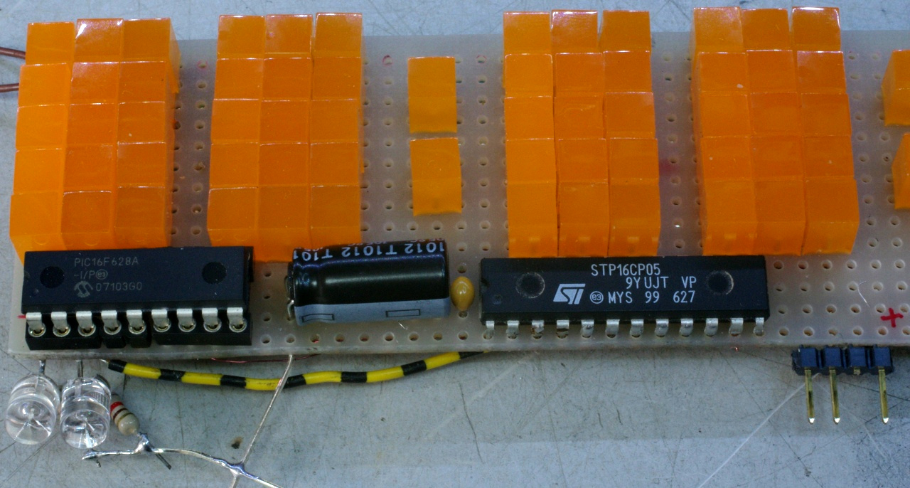
At the bottom left my two test LEDs are still there. The DCF LED is still functional in the code, the yellow TETS (sic) LED is not but could be used for DST indication or something. The light patterns are just lovely:


The colon is flashing during syncing and is solid when synced to DCF time.
Future developments? I discovered that 5x7 LED matrix displays also can be used when rotated horizontally:

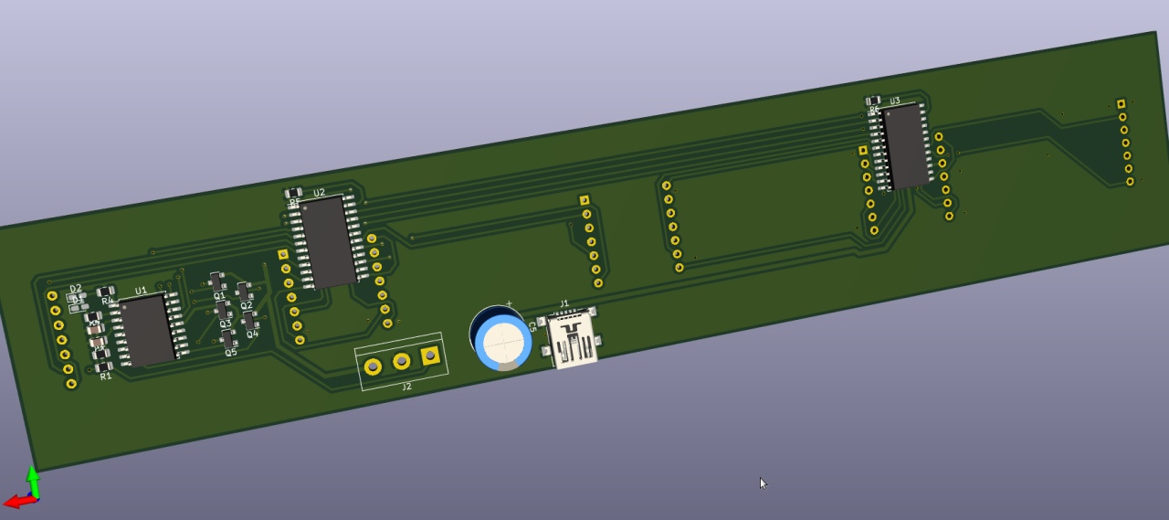
Only the last column is not used, and of course the columns between the numbers. Then I could design a nice PCB layout with SMD PIC and STP because the DIL version of the latter is not made anymore.
Update 27 December 2019:
I used the Kingbright TA20-11SYKWA displays to build a new clock. See the movie! And the KiCAD schematic! But... I discovered that the ROWS are connected to the wrong columns so all my hard work was for nought:
Update 1 August 2020:
Oh boy... so much happened! The world got hit by a pandemic and I got a bad batch of 5x7 displays. While I got my money back (thanks, Mr. Jack Ma!) I could keep the modules which were useless. They lay in a corner taunting me the whole time. Not willing to toss them I decided to put them to good use. The problem with the modules was that the rows were anode and not cathode as this diagram shows:

The only way to fix this was to swap the polarity for the rows and columns. The rows are now driven from the low side by N-channel MOSFETs (2N7002) and the columns are driven from the high side by HEF4094 shift registers. The drawback is that each column needs its own current limiting resistor (in this case 330R), something the STP chip does for you:

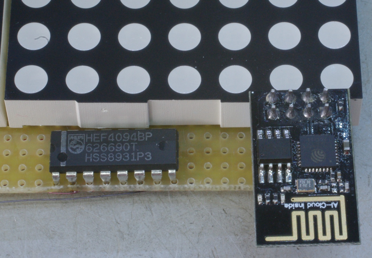
The ESP01 module takes the place of the original DCF77 generated by a Raspberry Pi. The excellent TX Tempus program cloned and ran without a hitch on my RPI 2B and later 3B. But I still needed an extra device. Then I came across this Elektor project. It is based on an ESP8266 module called ESP01, programmed with an Arduino "sketch". This posed a major problem. Being a PIC man I'm not a fan or Atmel so Arduino has no place on my Linux system. However, to program the ESP01 I needed the IDE. The "sketch" cannot be compiled any other way. It took me lots of searching, cursing and swearing but three frustrating days later I had a binary. Then I had to program the ESP01. It turned out to have a bad bootloader. This seems a recurring theme with these modules. Using esptool (native Ubuntu Linux!) I flashed the v1.2 bootloader (the others didn't work) at 74880 baud (!) and was rewarded by the IDE willing to upload the compiled "sketch" into the ESP01 using a specially built jig featuring a button to GPIO0 to bring it into flash mode. Fortunately, the ESP01 immediately connected to my WiFi as evidenced by the serial comms (9600 baud) it spat out though my programming jig into minicom running on my Ubuntu MATE lappie. Make sure to set handshaking to OFF.
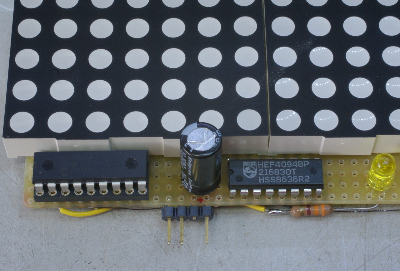
The hardware itself is straightforward. I found some very vintage real Philips HEF4094s and made frugal (just like current PM Rutte) use of prototyping board to mount the displays:

The code for my PIC had to be modified as well. The ESP01 code apparently cannot do interrupts so in contrast to TX Tempus it is not capable of producing a continuous DCF77 signal while also acquiring NTP time. Something a DCF77 receiver will do without issue (unless there is too much interference which in my case is abundant). My code did not like the interruption of the time signal one bit and it took me quite some effort to harden my code (asm) so it would not get upset by the interruptions. And to decode the time from the first DCF77 frame it gets when powered up. To troubleshoot my code I made a few movies (like this edited one showing missing minutes). Note the ESP01 module flashing its blue LED as it sends serial data when it gets its NTP fix. Also see the colon flashing or alternating to show it not knowing the time or having lost its signal.
Now I only need to fix my KiCAD design...
Back to the homepage
Date: 25 September 2019, updated 1 August 2020

This software is licensed under the CC-GNU
GPL.