The Clarville Dissected
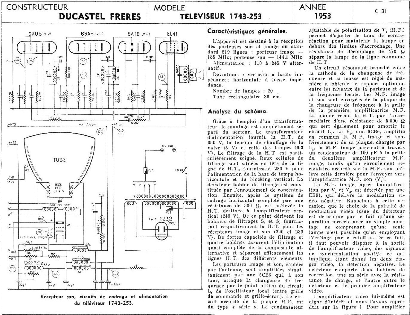
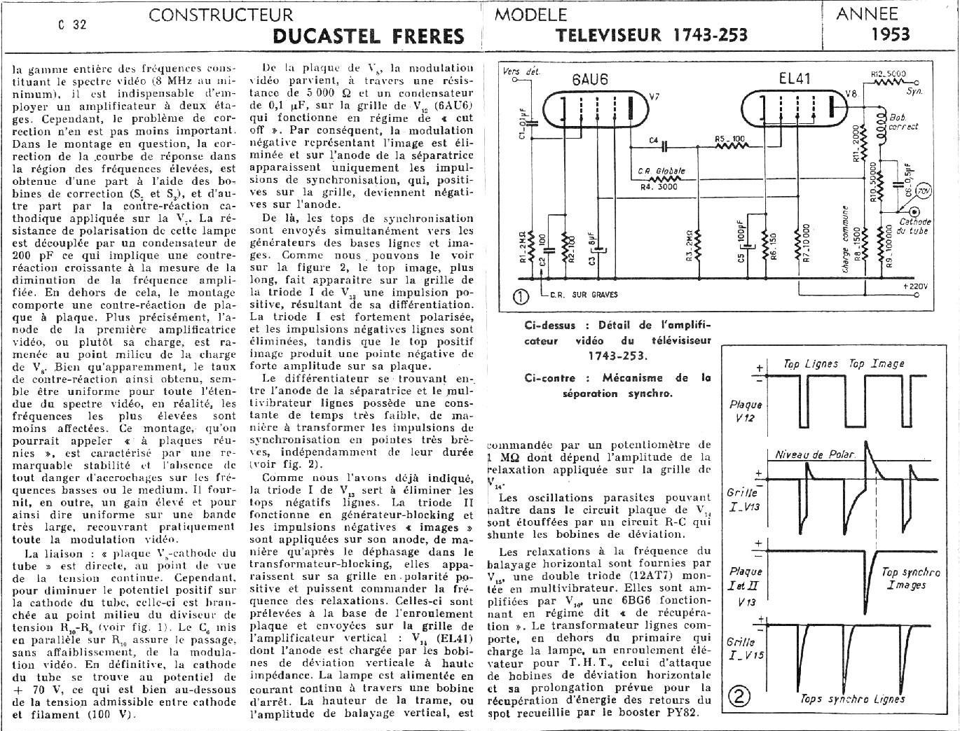
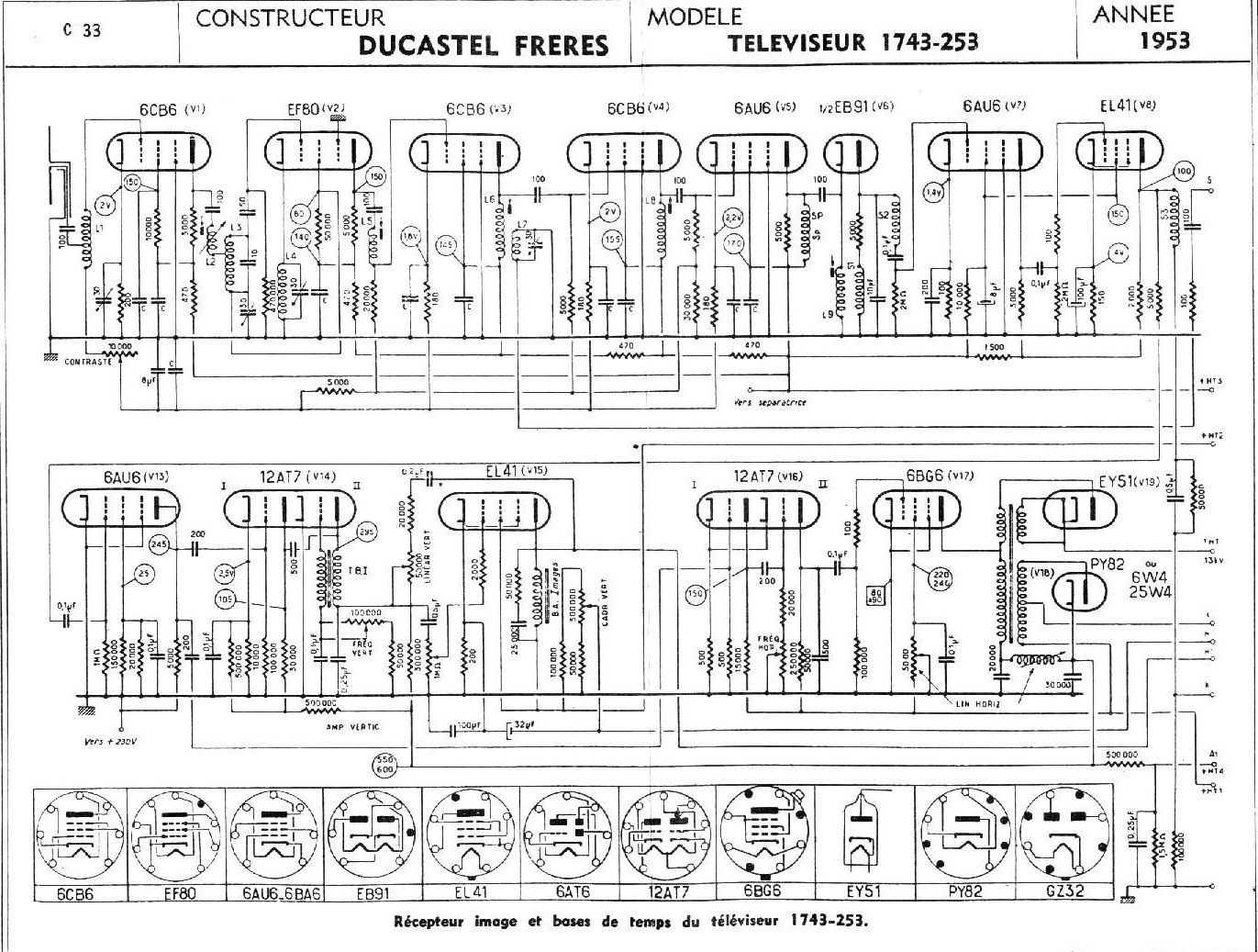
Since I could not find any documentation whatsoever I decided to reverse engineer the set. I first set out to sketch the chassis, then the power supply and finally the schematic itself. Someone had very helpfully posted a description of a similar set, the prosaically named Ducastel Téléviseur 1743-253:
So now I have a comparison, and the Clarville isn't even close:

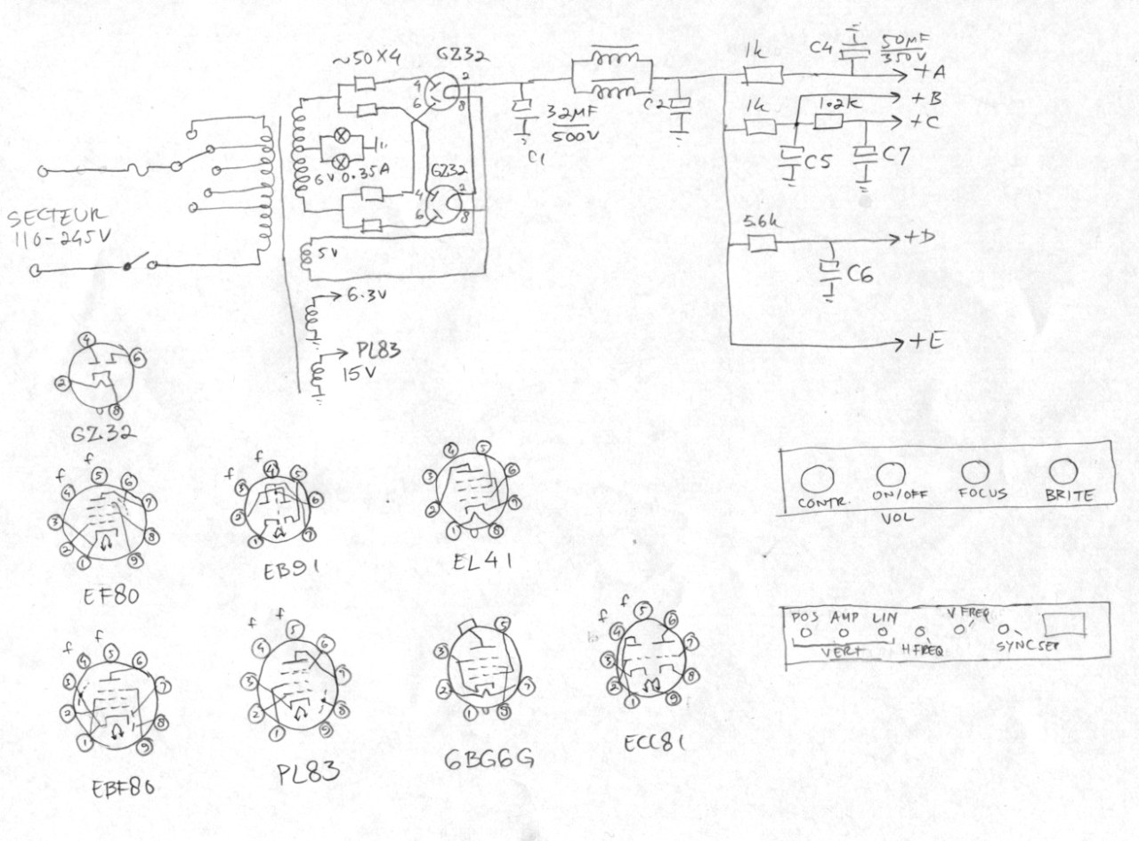
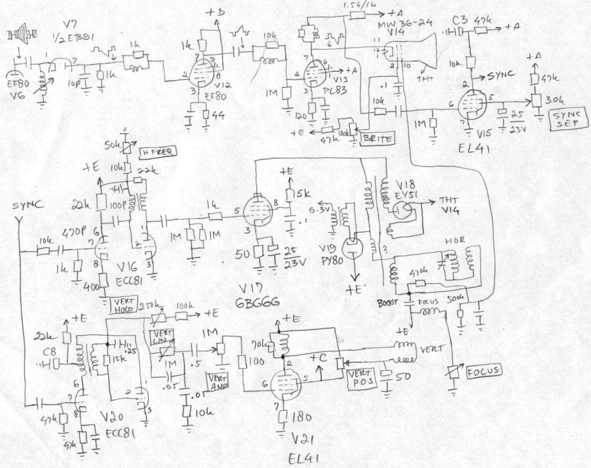
So far, so good. Most of it is still sort of similar, but the frame circuitry is completely different, as is the horizontal oscillator. There is a wiring error, the VERT AMP control is wired the wrong way around (compare the Ducastel). Since the LOPT has a burnt out wire I'm not sure about the winding between the booster diode and the deflection coils. But otherwise there can't be any boost voltage so it must be there. I'll see when I attempt to fix it.
A control that puzzles me is SYNC SEP. I've never seen this before, maybe it's there because an EL41 power pentode is used. Then again, my Philips TX400 uses a ECL80 as sync separator. There are two power pots: the FOCUS control and VERT POS. These are both huge wirewound units.
My plan is: fix the LOPT, fix the line oscillator transformer (aaaagh!!!!!), fix the top cap of the 6BG6G, its connector and the socket of the second GZ32 and replace the booster capacitor. Then disconnect the RF/IF strips, and gently reform the electrolytic capacitors using a variac. Check for frame and line activity and try to slowly bring the set to life. Once I've got light and deflection I can try to inject a video signal into the grid of the PL83. The picture tube tested good with my CRT tester.
Update 2 January 2014: I've got results!
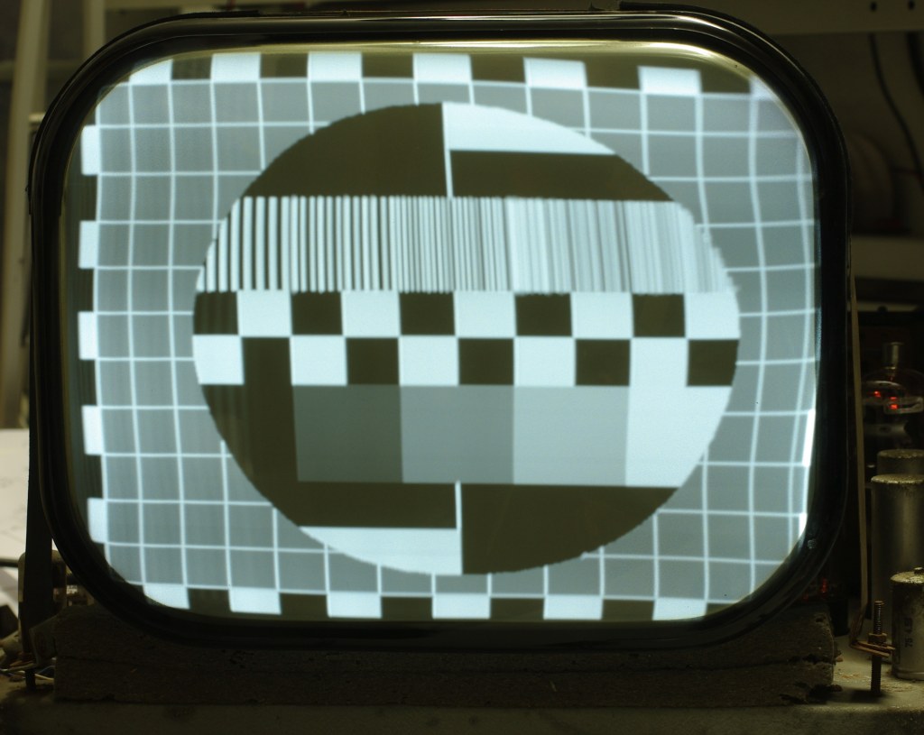
Still
some work to do, especially the horizontal scan timing sucks. The scan starts
and stops too early. Maybe delay the sync a bit so it starts later.