Modding a Philips 22AH180 Tuner
Someone challenged me with this tuner. It is a member of the Black Tulip series, which feature the at the time (early 80s) very hip 19" mounting tabs. To my amazement I found one on sale for repair. I just could not resist...
The original complaint was no search tuning. I found a good scan at Wil Manshande's great schematics/manual site. I found that the schematics had errors in them and I fixed them:


I found that there was no output at all. This was caused by the Hitachi output relay having gone phut. These relays are failure prone and this was no exception. The issue with search was caused by oscillation in the AGC circuit. This was fixed by adding an extra capacitor across C218. The discriminator also needed a bit of tweaking. Then, the circuit controlling the input attenuator had a too narrow Schmitt-trigger action. This caused it to toggle itself on and off. Replacing R247 cured the erratic behavior. Finally, there was a ripple on the +8 V line caused by fuses that had developed a high resistance over time. They were also the wrong value. These are nasty faults to find. The last three images are the two linear phase LC filters (and ceramic filters) that were the original reason for this project. (click to embiggen)


")


As for those IF filters, I ran the IF strip through my VNWA3 network analyzer. Because the Japanese engineers who designed this tuner included two ceramic filters the response is OK-ish (click for full-size):

The red line is the group delay (1 µs/div) which should be flat in the passband to prevent distortion of the MPX signal. What the engineers should have done is make the ceramic filters switchable. This would create a NARROW and WIDE path for the IF. Depending on signal conditions the appropriate path can be chosen to get optimal results.
Then there was the issue of the case screws. The previous owner had it repaired by a ham-fisted person who had lost all the screws and replaced it with different, self-tapping screws. Fortunately he was also lazy and damaged only a few screw holes. The proper screws turned out to be ISO14585. The manual lists these so helpfully as 4N and 6N but they are 2.9 and 3.5 mm sizes.
The last item on the list were the lamps of the indicators on the front panel. Since the tuner was always used on FM its indicator and the MHz sign had burned out. I replaced everything with SMD LEDs:


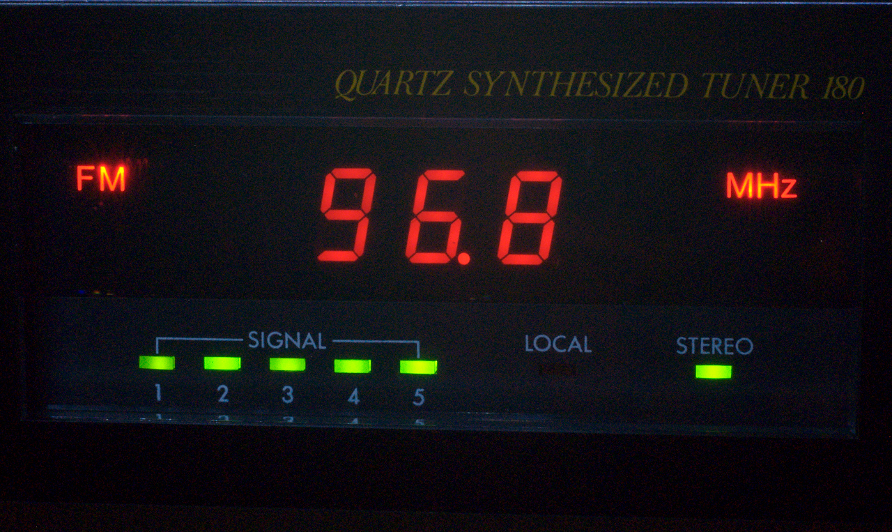
Finally I was awarded with a nice tuner! There was one tiny little detail nagging me: the 7-segment display. The 4-bit BCD data from the controller is converted to 7-segment LED display with a Toshiba TC5002BP. The decoder inside this chip omits the top bar (a) of the 6 and the bottom bar (d) of the 9, showing a "b" and a "q" instead (see also the two examples above):
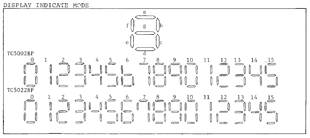
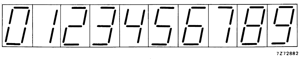
To me that is butt-ugly. The alternative TC5022B has an extra hook (f) with the numeral 7 so that one is out too. The HEF4543B does have those bars showing a proper 6 and 9:
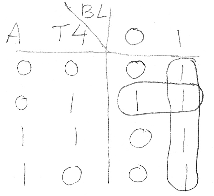
Unfortunately this is no direct replacement for the TC5002B because it has no RBI pin. This is a Ripple Blanking Input which allows the readout to be blanked in case of leading zeroes. This feature is used here. So I had to create the RBI line from the existing lines in the tuner. I had to dust off the knowledge I had about Karnaugh Maps to come up with a solution:
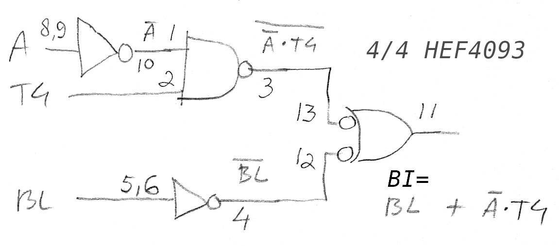
Once I had this figured out I could build the replacement module. I used cut off standoffs to create the plug for the chip socket. This was not such a good idea because when soldering wires to the pins they changed their orientation making that a challenge. Next time I will have to use a sub-subboard:


This finally produced the display I wanted to have!
The amount of work having gone into this tuner definitely was excessive. Worth it? You bet! It's a hobby after all!
Latest Update: 2 January 2021