Pentax Remote Clone
The replacement remote controllers for Pentax digicams can be had for as low as just $3.99. But having some old remotes lying around with a PIC16C54 in it I decided to have a go at it myself.
The
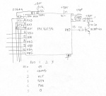
remote itself is deceptively simple:

Also, having found both information on how to "pop" a PIC (read the program with the protectionbit set) and how to generate a signal to fire the trigger on a Pentax digital camera ("Pentax F") I set out to try to read the PIC's contents. To no avail. I just fried the chip...
Oh well, let's start out from scratch. My limited programming skills hampered me greatly in generating proper assembly code. How would I use a timer to exit a loop that is only three commands long?
| LOOP | ||
| BSF IROUT | ; Switch on LED | |
| BCF IROUT | ; Switch off LED | |
| GOTO LOOP | ; Loop |
This lovely piece of code generates a 10 ms pulse with a repetition time of 30 ms, or 35.75 kHz to be precise, with my resonator (429 kHz). For the love of all that's holy I couldn't figure it out. Handling it from the interrupt routine would screw up my stack or it would put me back in the loop, so I ended up with a subroutine with 35 of these gems but with a NOP instead of a GOTO. Oh well... I ran into some other weird stuff: because of the schematic I had to configure the ports before setting the interrupts, otherwise the PIC entered a weird state (not sleep state because the oscillator was running) with all ports inputs. Also, while using the MPLAB 7.50 simulator I couldn't reset the RBIF bit in INTCON. I didn't look into that further as this posed no problems. The whole sad story can be seen in the code.
The signal is simple enough. A burst of 13 ms 38 kHz modulated infrared light from an IR LED, then 3 ms nothing, then seven pulses of 1 ms with 1 ms nothing in between. I called the subroutine (PULSE) which introduced short glitches in the signal, but the camera didn't mind and dutifully took a picture:

While trying to keep the circuit as original as possible I had to make three mods to it:

The first two are pulldown resistors for the two ports used to generate the wake-from-sleep interrupt (RB4-7 portchange) and the third the grounding of the unused port RB6. I also had to remove the socket I used for debugging the code as the two shells of the remote housing wouldn't close anymore. And I forgot to connect an important pin as well. That I found out later...
Final notes: using a device like the PIC16F628A is a bit overkill. An eight-pin 12C508 or similar would have been a much more sensible choice had I had such a chip available. And it really bugs me that I couldn't come up with a solution for a glitch-free output signal! I did have some code lying around that did that, but that used the internal resonator of 4 MHz and I wanted to use the original circuit. There was also the issue that every keypress produced two pulses. Maybe that was a bounce thing with the interrupt. Oh, and I didn't check the power consumtion in sleep mode. When my batteries run flat I know that this didn't work!
Back to the homepage
Last Update: 20 July 2008

This software is licensed under the CC-GNU
GPL.