Retro Tech: Rainbow Test Pattern
For some unfathomable reason I became interested in the rainbow and its brother colorbar test pattern. Now the confusing thing is that the colorbar is not the RGB color bars we al know and love but the rainbow chopped into bars to make color demodulator alignment easier.
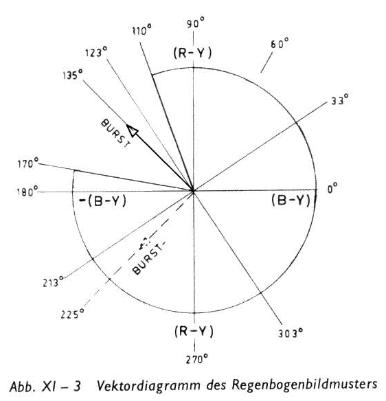
But first: what the heck are we talking about here? In the very early years of color TV, when the sets were massive cabinets full of vacuum tubes, these behemoths needed servicing often. Alignment drifted over the years and obscure faults needed some serious troubleshooting. To do that you need a test pattern. This will present a stable signal that will allow to compare measurements as you probe away inside the innards of the misbehaving set. In those days field service was the norm so a small, portable piece of equipment was needed. Technology at the time was very basic and the first test pattern generators, while portable, also used vacuum tubes. An example is the Heathkit IG-62. It was difficult to create the various timing signals using analog dividers. The solution was to use an oscillator with an offset of one f(h), or line frequency, below the color subcarrier of 3.579 MHz. This would then be 3.564 MHz. Because of this difference the phase would make a circle on the vector diagram, as illustrated in the manual for the Philips PM5507:
On the CRT of the TV this would show up as a rainbow image:
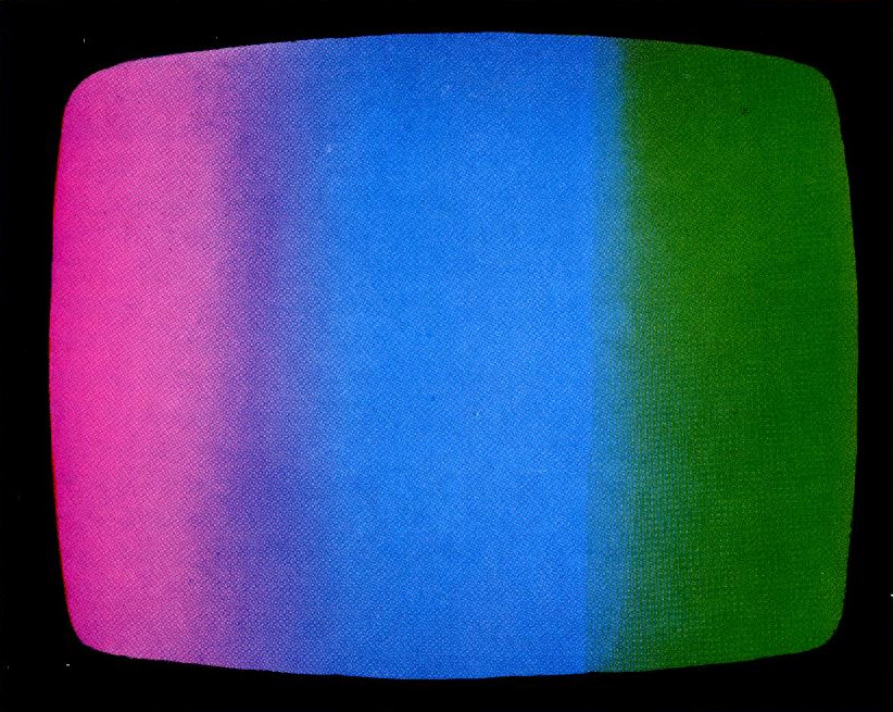
Again taken from the same manual. So when I came across one of these generators I could not resist and bought it. As no-one knew what it was for it was dirt cheap:

It needed some work, the cover of the frequency dial is gone and needs recreation, the feet were completely worn through and the sharp metal brackets poked through the degenerated rubber. I put new feet under it, kludged a video output on it:


and was rewarded with a nice rainbow:
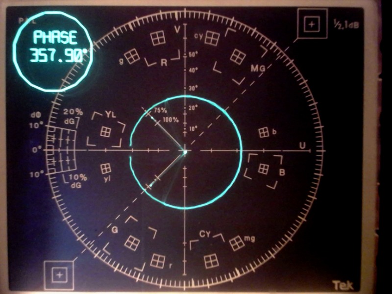
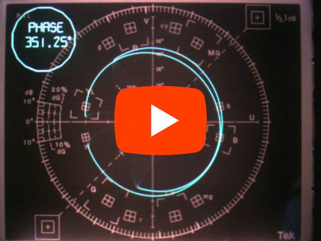
This is a screen capture with a USB video dongle. I immediately hooked up my wonderful Tektronix 1781 vectorscope:
The PAL bursts show nicely albeit distorted due to the harsh switching. The fun part is that while the NTSC version needs only one unusual frequency, the Philips needs two. This is caused by the PAL switching which (as you may know) is a refinement of the NTSC system and results in the tint control being redundant. All phase errors are compensated due to the phase switching (PAL stands for Phase Alternation on Lines). Needing to special crystals with unusual frequencies of course is a cost issue. The rainbow signal was not used extensively because the real color bars showed up in test equipment real soon when electronic tech developed new circuitry. The nature of the signal prevents usable measurements as there is no reference. The RGB color bars do have a reference and are much more convenient.
The "COLOUR BAR" of the PM5507 of course is the chopped-up version of the rainbow pattern:
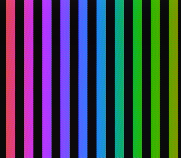
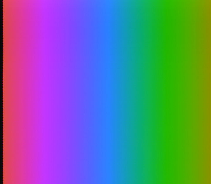
Then things got out of hand. I use a Raspberry Pi to generate testpatterns (PA3BWE's pi-atv) so I wondered whether I could create the rainbow with it. I kludged together a spreadsheet to calculate the RGB values for each part of the circle traveled during a line time period (64 µs of which 52 µs is active video). With some Linux script trickery I fed it to GIMP and created the rainbow as an image:

On the USB dongle it came out like this:
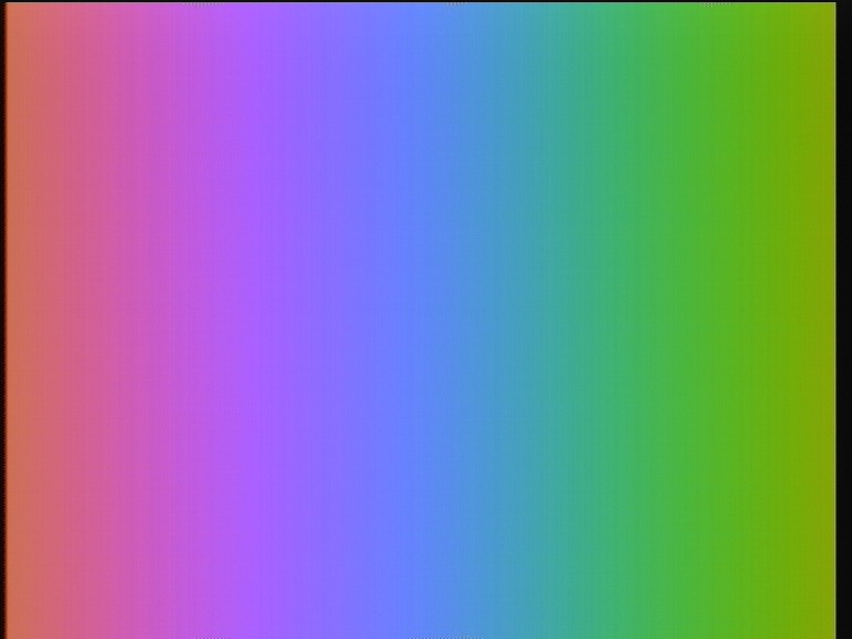
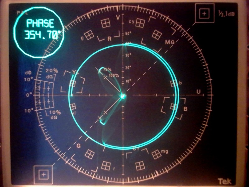
Apart from the crop on the sides it is picture perfect! The vector display showed an interesting limitation:
On the left clipping is visible due to the image values reaching 255.
But still I wasn't done. Because the PM5507 uses the difference between the two subcarrier frequencies to generate the sync signals, I wondered if I could use an Si5351A driven by a PIC to generate the frequencies. And I could! Another spreadsheet to calculate the synthesizer parameters (forgot why I needed the BAD in the result column):
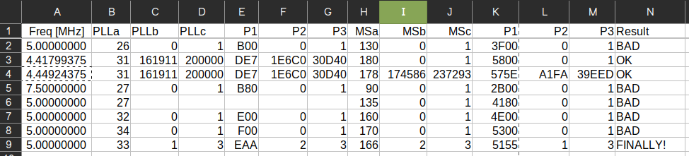
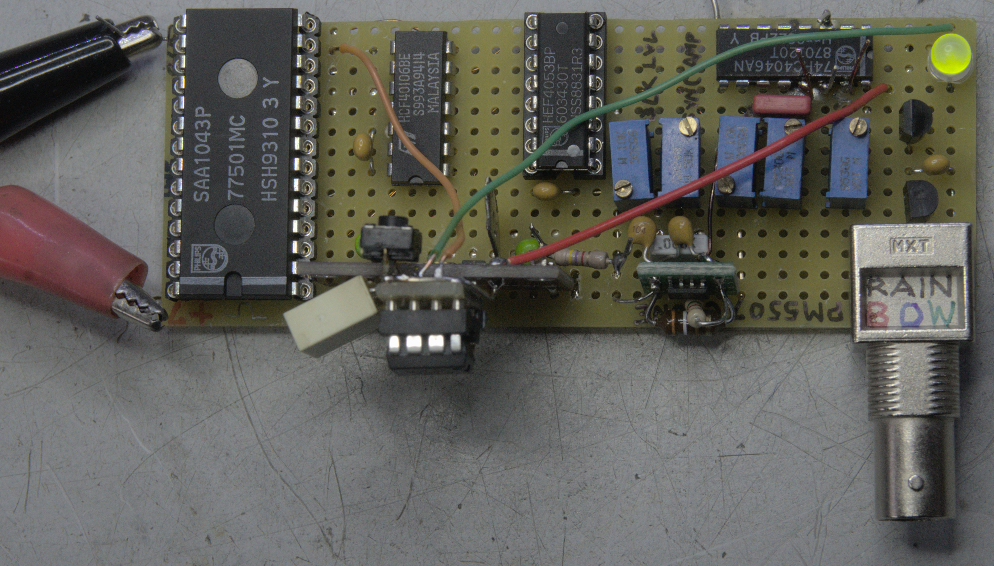
and my program (asm) was good to go. Of course I needed some hardware too. I have a couple of very vintage SAA1043 sync generator ICs in my tray and that is why I need the 5.000 MHz. The hardware was quickly built:

But there was a problem. Because the horizontal frequency is not locked to the subcarriers the phase is random and the color decoder of the TV cannot lock onto it. I put the project aside for a few months until I realized that the difference frequency of the subcarriers can be used to detect the phase. The SAA very nicely has a 2f(h) output that can be used to drive a phase detector. I chose a 74HC4046 because it has a phase detector that goes Hi-Z when not active. The SAA is "nudged" into the proper phase by skipping a few clock pulses:
But it did not work. If the phase leads (or lags) the detector gets stuck in only positive pulses. This ruins the detection! Eventually I solved this by forcing the detector to go through a complete cycle, detect the phase flip and then search for the right voltage out of the phase detector. A movie shows this nicely:
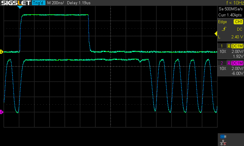
The whole process on my scope:
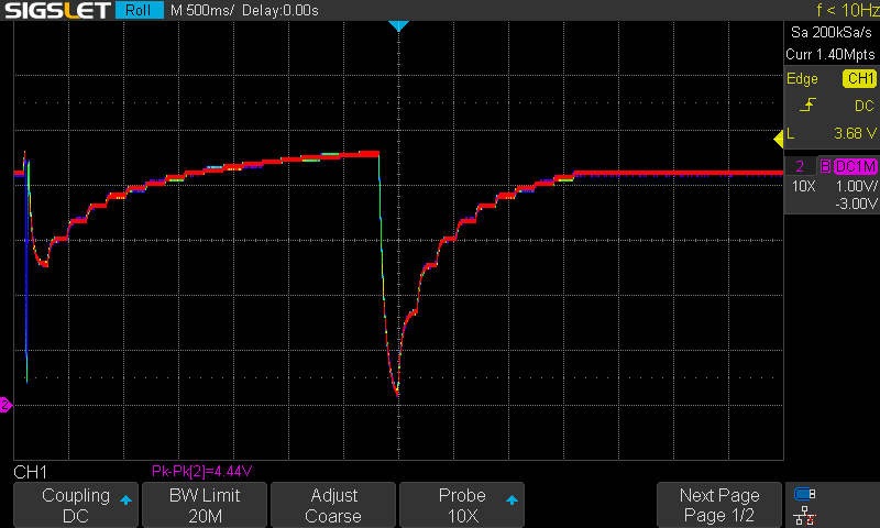
In this plot, the RESET button is pressed and the PIC nudges the SAA through a full cycle. Then the phase flip is detected and the PIC stops nudging at the right voltage level.
This is the additional circuitry I needed:

The subcarriers are mixed in the SA612A, the difference filtered and amplified and fed to the 4046 phase detector. The PIC then samples the resulting voltage and stops nudging once the right value has been reached. Then the bicolor LED turns green:
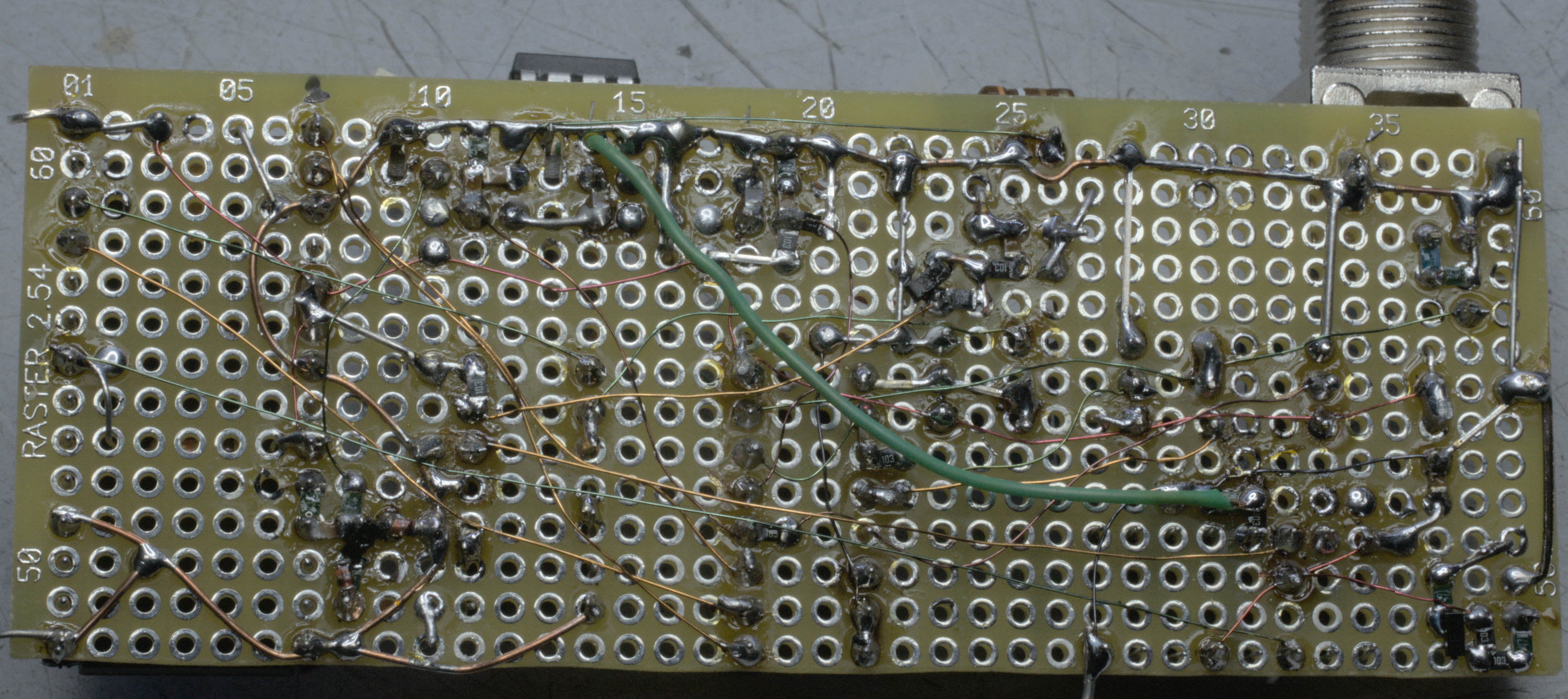
And the horrible bottom tangle:
Epilogue
Is there not an easier solution? Of course there is! By foregoing the 5.000 MHz from the Si5351A and building a VCO with the SAA I could have used the PC2 voltage to control the VCO. Because the phase will vary the 4046 will not remain stuck in one polarity but function as a frequency detector. This is how it is intended.
Finally, why the "I hate rainbows" title? Well, there is a brilliant scene in the South Park episode "Weight Loss 4000" where Cartman goes all out declaring that he hates rainbows after which Stan asks him "What the fuck are you talking about?"
Back to the homepage
Date: 16 February 2024

This software is licensed under the CC-GNU
GPL.