Medium Wave Mini Transmitter
With the switching off of the big MW transmitters this ancient band has become the playing field for all kinds of local initiatives by radio enthousiasts. The collector of vintage tube radios is not left in the cold. Even so, being able to play your own content is sometimes wanted. There are many designs floating around the internet including PIC controlled PLL transmitters. The PLL drives a modulator using a CMOS 4053 triple two-port analog switch. I wanted to try this concept, proposed by Otto Tuil, for years but did not bother to get the PIC needed (PIC16F690) and just flash the firmware into it. So I decided to write my own.
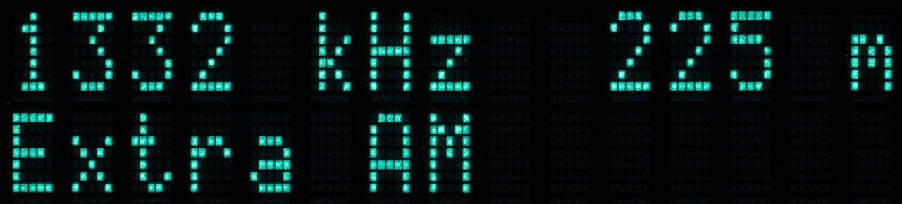
In my tray I also found an Adafruit module with an Si5351A clock generator. This neatly generates the frequencies needed to drive the modulator. However, programming the damn thing (over I2C) is not an easy thing to do as there are many parameters that need to be set. Luckily I could bring that down to 8 bytes per frequency. Now the medium wave broadcast band has 122 frequencies (in Europe/Asia) which means that these 122 config words fit in four 256 byte pages in a PIC. There is even room for a wavelength table. This is a neat feature because vintage tube radios have the tuning dial in meters instead of kHz. The frequency and wavelength are then printed on an LCD:

Two buttons select the frequency. The schematic is simple:
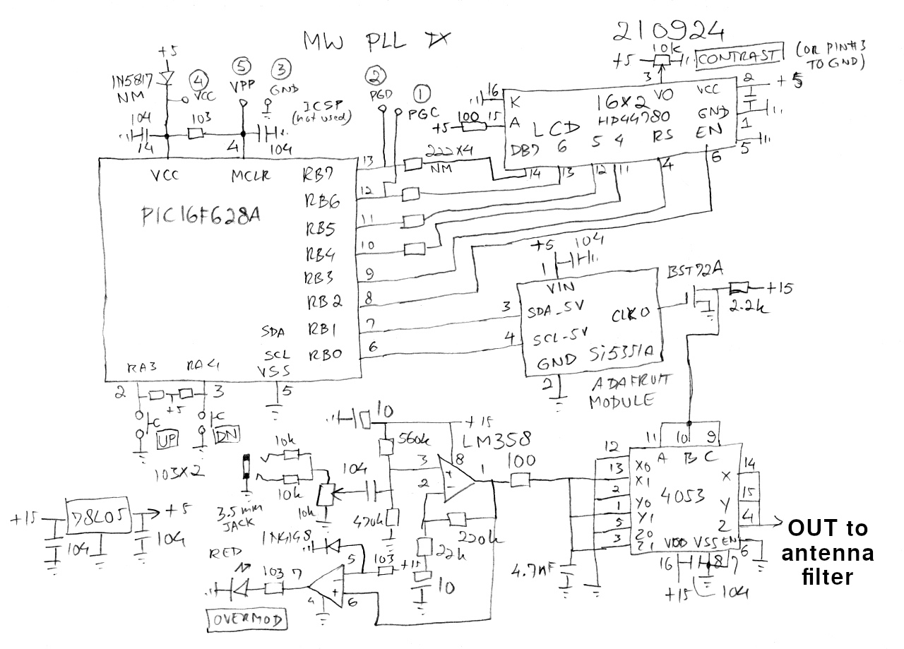
The PIC controls the I2C bus and sends the text to the LCD. It also scans the two buttons. The audio is amplified and fed to the 4053. A LED provides overmodulation indication. Finally, the output is fed to an antenna filter (TODO) which filters the square wave from the CMOS switch and provides matching to the radio connected to the modulator. This is either a lowpass filter or a tunable LC filter.
The firmware for the PIC is also straightforward. After initializing the PLL and LCD it becomes my beloved state machine running on an interrupt (TMR0) and scanning the buttons. The data for the PLL was generated using Silicon Lab's Clockbuilder program running on a win7 VM. This is a rather annoying tool which I had to run to generate the parameters for each frequency. The data was then copied into a LibreOffice spreadsheet, exported to CSV files, edited and fed into MPLAB to create the program (asm) and to generate the HEX file for the PIC. There is just one thing left to do and that is design a nice PCB for this project.
Update:
As I gave my mini TX away and my favorite local radio station, Extra
AM (1332 kHz), was plagued by a borked antenna I decided to build a new
one. This time with the 4053 working on 5 V and driven directly from another
Si5351A:
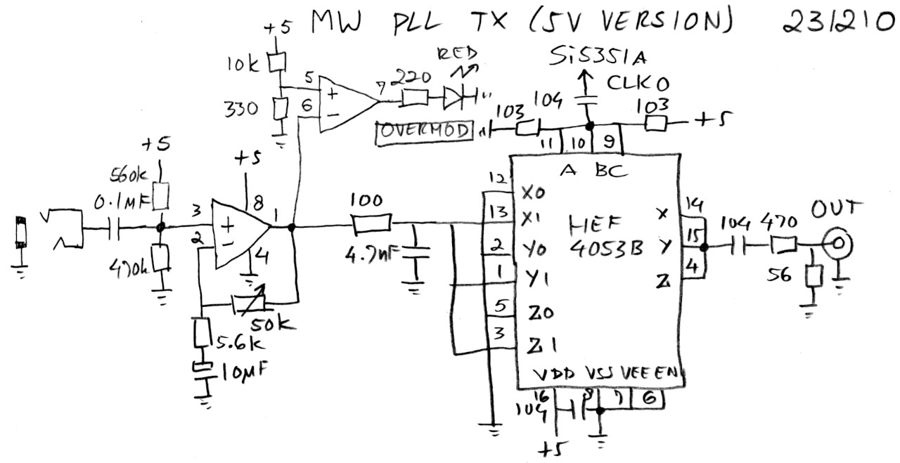
The PIC and Si are the same so they are omitted. Display now is a VFD module, fortunately with identical pinout. As I had some space left in my PIC I wrote a dedicated Extra AM version (asm) with the station name in the display:
Because I still had some bytes left I also added the original frequencies for Radio Luxembourg, Radio Mi Amigo and Radio Veronica. Now there are only 9 bytes left...
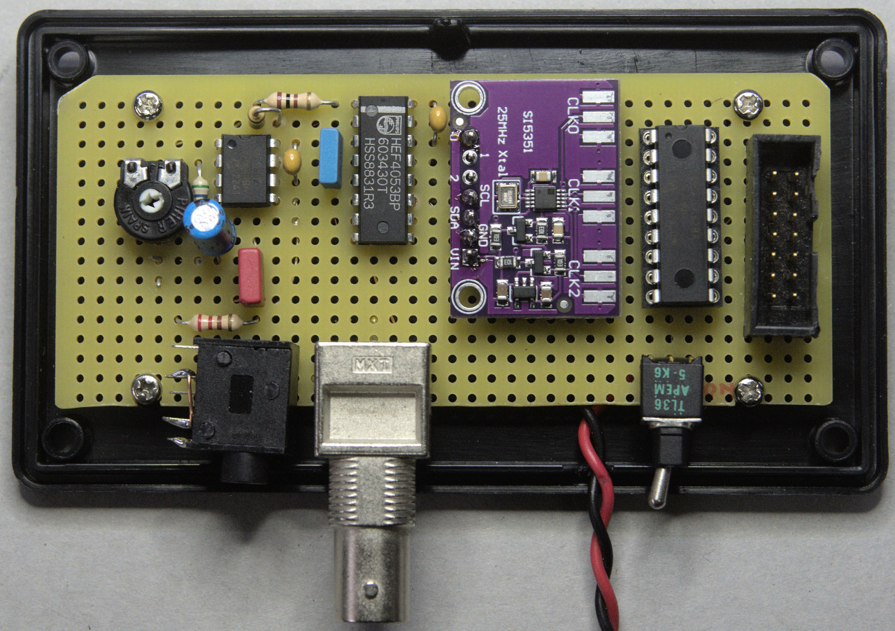
Once that was done I completed the PCB:
There were some issues that I had to solve. The original LM358 is not rail-to-rail so I replaced it with an MCP602. The Si only does 3.3 V output which needs a trick to have the HEF accept the logic levels. And the output of the HEF now has an attenuator. Which brings me to something I did not address in the first version: the output filter. The HEF output is a modulated square wave riding on the original modulation. This cannot be radiated into the ether. Also, coupling the signal to a radio, whether a vintage tube radio or a more modern solid state radio with a ferrite rod, is fraught with issues like distortion and modulation hum. So I decided to use a tuned loop to get at least the magnetic field in my house. The current running through the loop wire will also nicely induce a voltage into a wire antenna of a tube radio. This is a really simple circuit:
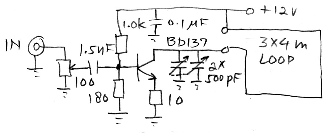
The tuning capacitor was an old one from my junk box. The circuit is built on top of it:
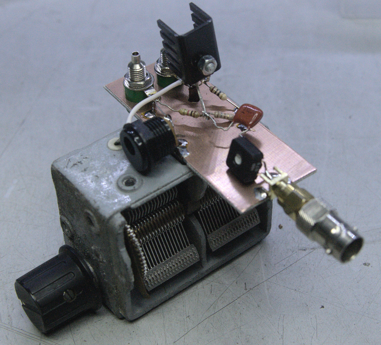
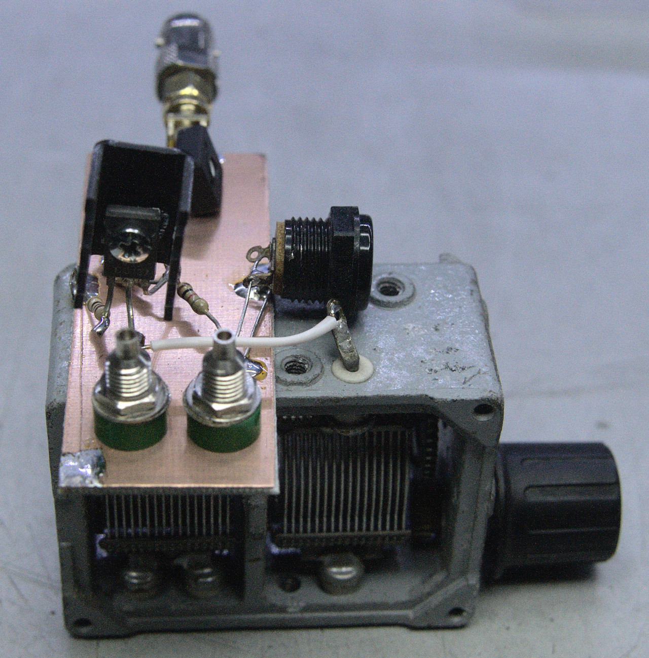
The tuned loop is plugged into the banana sockets. My loop has an inductance of something like 20 µH. The tuning capacitor will not get it into resonance below 1100 kHz or so. The loop can be widened to get it to tune lower. Care must be taken not to overdrive the amplifier:
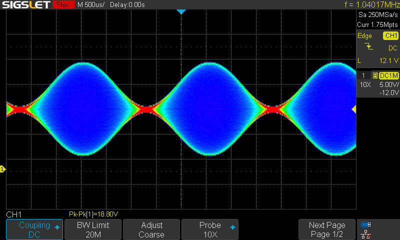
This is the collector voltage of the BD137 showing a nicely modulated AM signal. When overdriven the signal gets clipped:
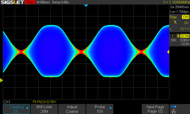
At this point, the signal will reach about 200 m. But the signal is clear and undistorted. Mission accomplished!
Back to the projects page
Date: 26 September 2021, updated 11 December 2023

This software is licensed under the CC-GNU
GPL.