Magnetic Lock Timer
For a "kinky" project (OK, a padded cell) I needed a controller for a magnetic door lock. This was to be mounted on the door frame. I searched around for something standard but all I found were consumer type mains timers or professional, expensive programmable timers. Which were way too big anyway. So I decided to "roll my own".
Enter my favorite controller, the trusty PIC16F628A. Having gained some experience with this Microchip chip I decided I could tackle it. The hardware is easy: just hook up a dual 7-segment display (FWIW: a LEDbright BD-A504RD liberated from a junked digibox) to PORTB and two PNP transistors to two PORTA lines and off you go. I didn't even go through the trouble of creating a schematic diagram. The cathode resistors are 220 ohms, the base drive resistors 1.8k and the reset and switch pull up resistors 27k. The segments are tied together and the PNPs drive the common anodes of each section. The magnet is switched with a logic MOSFET taken from a scrap motherboard.


Of course, what I wanted was never done before but many similar setups were made across the interwebs. I split the program into two parts: the interrupt routine for the display and the handler for the time housekeeping.
The functional specs were easy enough: when idle show a dot, when the button is pressed activate the magnet and increase the countdown time by 0.1 hour and after 10 hours by 1. The countdown starts immediately and once done the magnet is switched off. At powerup a lamp test is shown. Pulling CLR low with a second switch resets everything.


The debounce routine gave me some headaches, in the end I didn't solve it to my liking but it was functional so I left it at that. I had a similar sensation with the time housekeeping. I should have used the DECFSZ routines but my 7-segment display routine made that impossible. This would have been solved easily with a simple offset but I did it the hard way. Finally, to make sure the controller doesn't hang I used the watchdog timer which gets cleared every multiplex (display) interrupt.
Other than that there's not much to be said. The code is straightforward and can be found here (with pretty colors, Notepad++ is really great!) or as asm file.
Update: PC Board!
To enable easier assembly I decided to create a schematic and PCB:
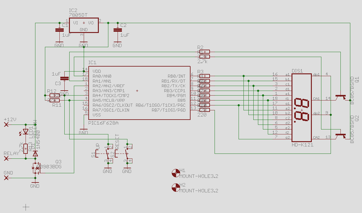
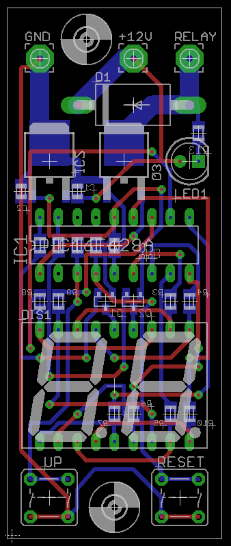
Unfortunately, I made some errors that of course only showed up once the boards were manufactured. Still, the end result is pretty:

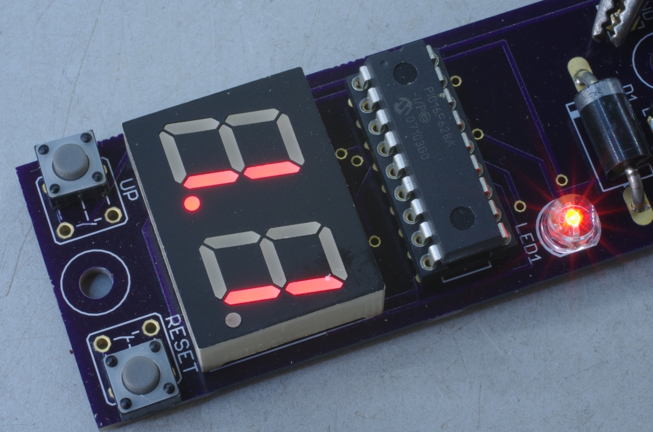


To assist the SMA (surface mount assembly) I had a stencil made for the application of the solder paste. This works beautifully! Then populating the board and popping it into the Weller reflow oven (discarded by my employer) is effortless and insanely fast. Once set up, creaming, populating and soldering takes only a few minutes per board. Then mount the few thru-holes and I'm done. I can start a webshop now! Yay! For inquiries contact Tjerk.
Another update: Bugfix release
I discovered several issues with the code. First of all, I never go past 10 hours so I removed the associated code. Then I found that after a reset, first the lamp test is executed and only then the FET is switched off. When the reset is issued by an external device like fire alarm this is not acceptable. Finally, the timer was a bit off so I adjusted TIMER1 so it would run faster. The updated code (version 1.2) can be found here.
Back to the homepage
Started: 16 June 2011, Last Update: 27 August 2018

This software is licensed under the CC-GNU
GPL.