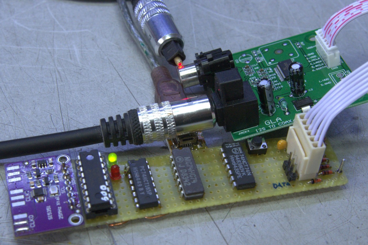
I2S Test Generator
I needed a test signal for sound leveling for A/B testing amplifiers and the like. The generator is based on a 1002 Hz generator which pumps 44 samples at 44.1 kHz sample rate to my Wolfson WM8055 board which then converts the I2S to SPDIF. It is based on an Elektor design which has the samples in the code of an Atmel controller. I decided that I wanted a lookup table which posed some issues. Then I really ran into trouble.
You see, the Wolfson chip's documentation is pretty horrible. The information is there but it's all over the place. The most important issue, how to master clock the thing in slave mode, is not documented. Someone told me the clock must be 256*fs, which is 11 MHz. So I used an Si5351A to generate the 22 MHz clock for the PIC and the 11 MHz for the Wolfson. This would sometimes not work because the phase of the 11 MHz could flip and the timing of the I2S would go haywire. So I had to use an extra 74HC74 dual flipflop:
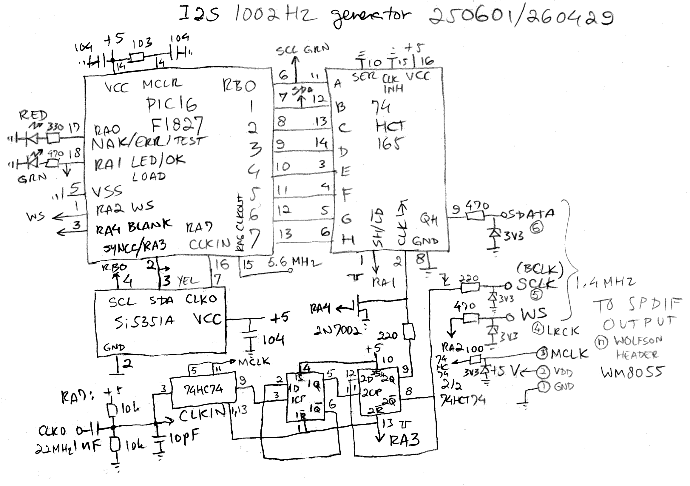
Another issue I had to tackle was clocking out the 74HTC165 shift register. The clock and load pulses would not tolerate each other so I just blanked the clock input with a MOSFET during load. I could have used a gate but a MOSFET is smaller. The four flipflops are cleared (SYNCC) before the data is put out to ensure proper synchronization with the Wolfson.
What also didn't help is that the Si and the Wolfson expect 3V logic. Unfortunately the HCT series CMOS chips only work at 5V so I had to devise an interface to clock the PIC from the Si and limit the signals to the Wolfson with zeners. I did not want to try the 5V tolerance of the Wolfson...
The first iteration of the code (.asm) used a PIC16F628A. Now this PIC has the RMW issue. The Read Modify Write issue means that when setting a bit on a port, the port is read, modified and then written back. This can cause other bits on the same port to flip due to parasitic capacitances. You cannot make this up... So I chose the PIC16F1827 instead because it has latch registers which do not have this behavior. These registers are in bank 2 but with taking proper precautions (like having the index register on address 0x70 which is accessible in all banks) the port bits can be manipulated directly. It also allows clock switching so it will clock itself until the Si starts generating its 22 MHz clock.
Once I got this figured out I just copied/pasted code I wrote previously (the Si5351A) and after many revisions it worked. The table was generated with a small program written in QuickBasic 4.5. The parameters for the Si5351A were generated with Silicon Labs' ClockBuilder.
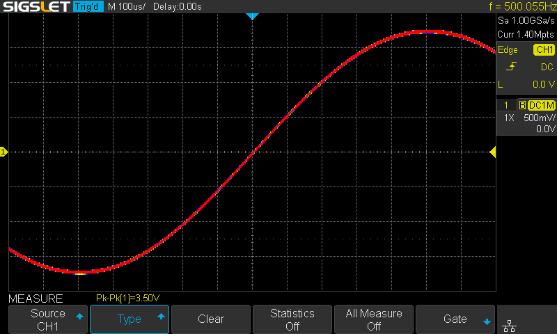
Now I had a 1002 Hz signal. I had two issues with that: it was not exactly 1000 Hz and it was also not 500 Hz which is less harsh to my ears than 1 kHz. So I created a new table with 441 samples of 500 Hz. To get it to work I had to cut up the table into four pieces because the RETLW instruction only returns from at most 252 bytes or so at a time because of 8 bit addressing. This is another reason I chose the PIC16F1827 because it doesn't have the PCLATH preload requisite the 'F628A has. Once I had solved (.asm) the timing issues due to skipped GOTOs I had a clean 500 Hz test signal:
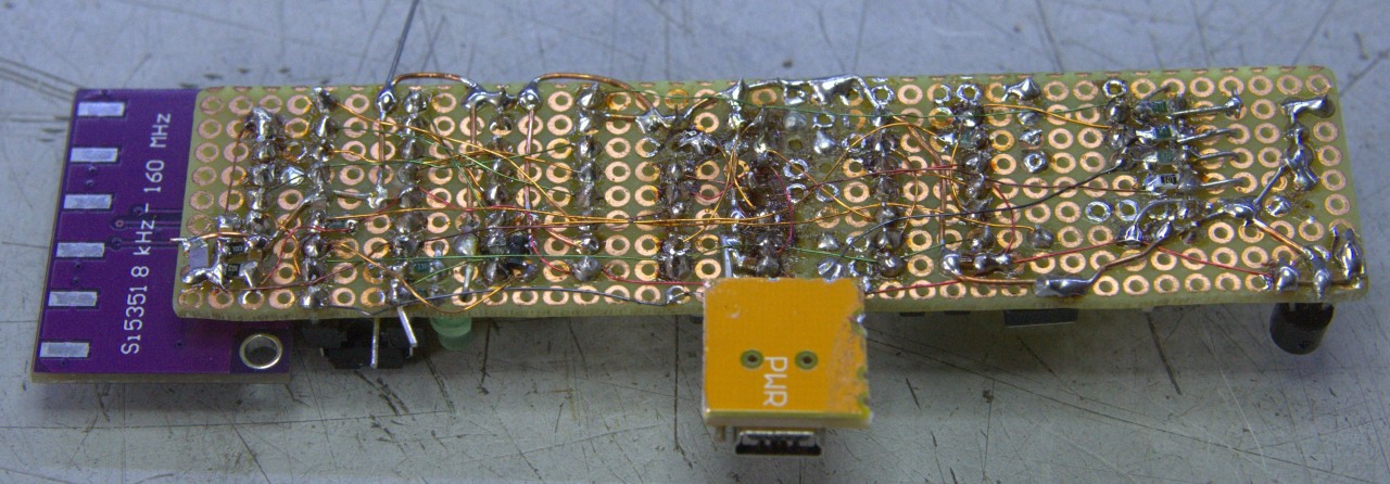
And now all that's left is a nice boxie:
Back to the projects page
Date: 18 May 2026

This software is licensed under the CC-GNU
GPL.