Modding a Tosh Power Brick
Sometimes you need a power supply with a specific voltage but the junkbox doesn't contain it. It does contain Switch Mode Power Supplies, also known as Power Bricks for laptops. Sadly, the voltage of all the power bricks are wrong.
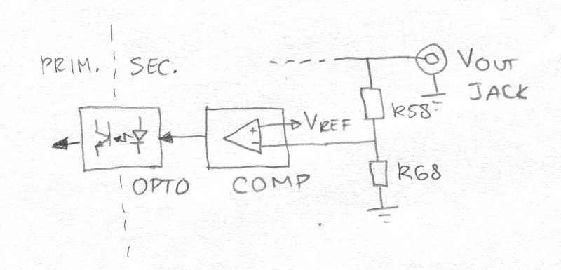
This can be fixed. In my case I needed 12.0 V to power one of those Chinese LED strips (with SMD 6-pin LEDs on them). It's important to feed it the right voltage because the LEDs may burn out if given too much juice. The Toshiba power bricks in my junk box generate 15.0 V @ 5 A, which is 75 watts of power and more than enough to light my strips. Now the fun thing is that you don't need to know anything about the schematic or the actual design of the SMPS. The principle is always the same! The only trick is to find the output voltage sense circuit. This come in many shapes and forms but always contain a voltage divider that feeds a portion of the output voltage to a comparator. This device compares this against a reference voltage. The output of this device invariably drives an optocoupler which in turn is connected to the primary switchmode control circuit.
In the simpler "wall wart" type of SMPS the comparator is usually the venerable TL431, an adjustable zener diode connected to the voltage divider and the optocoupler. It adjusts itself until the voltage at the divider is 2.5 V. The Delta-made Toshiba power brick contained a SGS-Thomson device marked "EZ550" and "DAS001". This is an 8-pin SMD with an internal 2.5 V reference voltage. I couldn't find anything about this device and the flash infested crap website of ST didn't help either.
Anyway, to find the new values of the resistors in the voltage divider they must first be located. This can be done by connecting the output jack to an adjustable external power supply. Then measure the connection to the optocoupler and start changing the voltage of the power supply. The beauty of this method is that the primary of the SMPS is not connected to mains power! If the probe tip of the multimeter slips the power brick won't explode or go phut in some other way. The secondary circuit is fully functional, however. Once the voltage reached rated value the comparator will start driving the optocoupler and voltage at that point drops. Now the Vref and divider voltages are about equal. Tracing the PCB the divider resistors can now be found. In the case of the Tosh power brick they turned out to be R58 and R68. I decided to change R58. This took some experimenting. The original value is 24.4 k, which is not obvious from the marking on the tiny 0603 part. To get 12.3 V I would need a voltage drop of 9.80 V. The designers of Delta chose a current of 0.502 mA so this would give R=V/I= 9.80/0.502=19.5 k. Putting a 100 k resistor parallel to R58 would get me real close. Unfortunately the EZ550 loaded the divider too much and the output voltage rose to 12.8 V. Picking a 82 k resistor solved this, voltage now hit 12.34 V. Nice. I used a new 0805 SMD resistor but your junk box may contain pcbs with the resistor on it. Carefully remove it and use it on the board. Clean one solder pad and using a tooth pick push the resistor down while heating the pas with the smallest tip you have. Then solder the other end and finally mount the parallel resistor on top of the first.
The procedure was simple. First crack open the case of the power brick using a vise. Then remove all shielding and isolation. Change the resistor, check functionality by plugging it in (careful with the mains voltage! The primary of the board is live) and loading the output with the intended load (my Chinese LED strips). Finally reverse disassembly and tape the case shut with duct tape. Cable ties work even better as these don't come unstuck. If needed cut away any burrs. Done!


